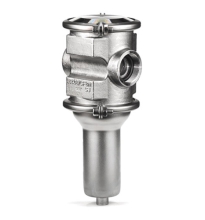
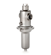
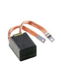
Bộ điều khiển động cơ DM365MA hãng Baishan China

0944911836 Ms. Duyên
0972835740 Ms. Hà
0385097045 Mr. Hiếu
0392468875 Ms. Anh
0707602728 Ms. Vân
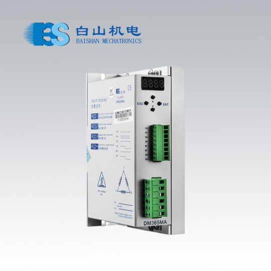
Bộ điều khiển động cơ DM365MA hãng Baishan China
DM365MA
The driving voltage is DC24V- 50V
The adaptation current is below 6.0A
-------Typical application---------
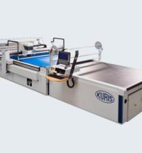
This product is widely used in engraving machines, small CNC machine tools, packaging machinery and other medium and small CNC equipment with high resolution.
-
DM365MA
-
Liên hệ
-
1492
- Thông tin sản phẩm
- Bình luận
product description
DM365MA is a three-phase stepper motor driver based on DSP control. It is a new generation of all-digital stepping motor driver composed of advanced DSP control chip and unique control circuit. The driver provides customers with 4-segment 7-digit LEDs and 4 buttons. Customers can set the parameters through the buttons according to the actual application. The set parameters will be automatically memorized, stored and displayed on the LED digital tube of the machine in real time. The driving voltage is DC24V-50V, and it is suitable for various types of three-phase hybrid stepping motors with a current below 6.0A and an outer diameter of 57-86mm. The driver adopts a circuit similar to the servo control principle, which can make the motor run smoothly, with almost no vibration and noise. When the motor is at high speed, the torque is much higher than that of the two-phase and five-phase hybrid stepping motors. The positioning accuracy is up to 60,000 steps/revolution.
Features
√ The input signal voltage is compatible with 5V—24V, and the maximum response frequency is 250Kpps.
√ With any electronic subdivision (electronic gear), the highest resolution is 60000/rev.
√ The drive current (RMS) can be adjusted arbitrarily from 1.2A/phase to 5.0A/phase.
√ The locking current is adjustable, and the adjustment range is 5%-100% of the driving current.
√ Single power input, voltage range: DC24V~DC60V.
√ Comes with 4-segment 7-digit LED digital tube and 4 buttons, which can set parameters such as locking current, driving current, and subdivision.
Pin function description
|
port definition |
pin number |
mark |
Function |
Notes |
|
Signal port |
1 |
PU+ |
Input signal photoelectric isolation positive terminal |
Connect to 5V-24V power supply, 5V-24V can be driven |
|
2 |
PU- |
BS04=1, 3, PU is the step pulse signal |
Whenever the pulse level changes once the motor takes one step, the input signal 5V-24 can be driven, no need to connect resistors in series, and the pulse width is more than 2.5μS |
|
|
BS04=0, 2, PU is the forward step pulse signal |
||||
|
3 |
DR+ |
Input signal photoelectric isolation positive terminal |
Connect to 5V-24V power supply, 5V-24V can be driven |
|
|
4 |
DR- |
BS04=1, 3, DR is the direction control signal |
Used to change the direction of the motor. Input signal 5V-24V can be driven, no need to connect resistance, pulse width>2.5μS. |
|
|
BS04=0, 2, DR is the reverse step pulse signal |
||||
|
5 |
MF+ |
Input signal photoelectric isolation positive terminal |
Input signal power supply 5V-24V |
|
|
6 |
MF- |
Motor release signal |
When it is valid (low level, on), the motor wiring current is turned off, the driver stops working, and the motor is in a free state |
|
|
7 |
RDY+ |
The driver is ready to output the signal photoelectric isolation positive terminal |
The drive state is normal, and the signal is valid (low level) when it is ready to accept the controller signal |
|
|
8 |
RDY- |
The driver is ready to output signal photoelectric isolation negative terminal |
||
|
Motor, power terminal |
1 |
U |
Motor wiring |
|
|
2 |
V |
|||
|
3 |
W |
|||
|
4 |
NC |
null |
|
|
|
5 |
DC- |
power supply |
DC power supply:DC24〜50V |
|
|
6 |
DC+ |

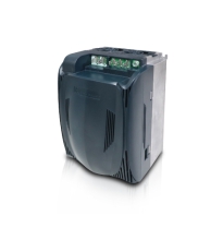
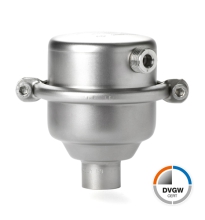
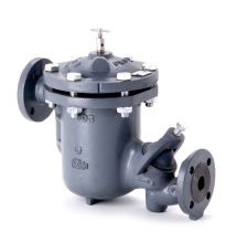
Sản phẩm cùng loại


Thông tin liên hệ
CÔNG TY TNHH GIẢI PHÁP TỰ ĐỘNG HÓA SAS
Mã số thuế: 0315763284
Địa chỉ: 409/48 Nguyễn Oanh, Phường 17, Quận Gò Vấp, TP Hồ Chí Minh,Việt Nam.  Xem bản đồ
Tên giao dịch: SAS AUTOMATION SOLUTIONS COMPANY LIMITED
Tên viết tắt: SAS AUTOMATION CO., LTD
Tag seo
Copyright © 2020 your name Designed by:Nina Co.,Ltd
online: 180
Trong tháng: 10000
Tổng truy cập: 4065524
