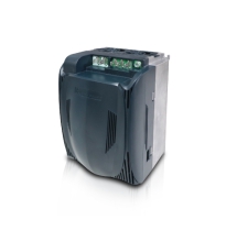
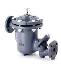
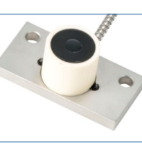
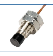
Cảm biến đo khí gas transmitter ADOS GTR 196

0944911836 Ms. Duyên
0972835740 Ms. Hà
0385097045 Mr. Hiếu
0392468875 Ms. Anh
0707602728 Ms. Vân
Cảm biến đo khí gas transmitter ADOS GTR 196
Application
The gas transmitter ADOS GTR 196 is suitable for continuous measurement of gases in normal areas and areas where there is a risk of explosion.
By employing 5 different types of sensor, noxious, explosive and non-combustible gases and vapours can be measured.
A current signal is generated that is proportional to the measured concentration of gas, which is transmitted to an evaluation unit placed in a safe area, away from any dangers of explosion.
The type test of the explosion-protected gas transmitter, is completed by the KEMA.
Test certificate: KEMA 03 ATEX 2403 X
Degree of protection: II 2 G, Ex demb [ia] IIC T6
Fields of Application
Chemical industry
Manufacture of paints and varnishes
Plastics processing plants
Sewage works
Gas-fired boiler systems
Liquid gas storage houses
Laboratories
Oxygen concentration measurements
Refineries
Cold storage houses (Ammonia monitoring)
Paint spraying booths
... and many more.
-
ADOS GTR 196
-
Liên hệ
-
926
- Thông tin sản phẩm
- Bình luận
TGS sensor
The TGS sensor contains a semiconductor sensor, which is constructed on SnO2-sintered N-substrate. When combustible or reducing gases are absorbed by the surface of the sensor, the concentration of the test gas is determined by the change in conductivity.
1 = Circuit voltage
2 = Heating voltage
3 = Load resistor
VQ sensor
The head of the VQ sensor functions on the principle of heat reaction. When combustible or reducing gases or vapours come in contact with the measuring element, they are subjected to catalytic combustion, which causes a rise in temperature; this rise causes a change in the resistance of the measuring element which is used as a measure of the component of gas being tested.
The inert element is for compensating the temperature and conductivity of the test gas.
1 = Catalyzer pellistor
2 = Electric connections
3 = Inert pellistor
4 = Diffusion filter
PID sensor
The sampled gas flows through a measurement chamber,
that incorporates a UV radiating source and a pair of
electrodes with opposing polarity. The gas molecules
to be detected are ionized by the UV radiation.
The resulting positively charged molecules and the
electrons are attracted to the relevant electrode. The current generated is a measure of the gas concentration.
Using the PID measuring head, volatile organic compounds (VOC) can be measured, the ionisation potential of which is less than the energy in the UV radiating source (10,6 eV), e.g. aromatic hydrocarbons like toluol (C7H8) and xylene (C8H10) as well as chlorinated hydrocarbons like trichloroethylene (CHCl3). The detection of toxic gases like phosphine (PH3) is also possible.
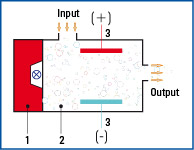
1 = UV radiating source
2 = Test gas
3 = Capacitive charge measurement
TOX sensor
The TOX sensor is a measurement system with an electro-chemical cell, where the sampled gas is measured by diffusion. In the case of oxygen measurement the oxygen content is reduced in an electrolyte, thus producing a small flow of current (electro-chemical process). At a constant air pressure, this current is directly proportional to the oxygen concentration in the sampled air.
1 = Anode
2 = Electrolyte
3 = Cathode
4 = Diffusion path
5 = Diffusion filter
6 = Test gas
The IR sensor
The test gas flows through a measurement chamber that incorporates an IR radiating source and a two-channel infrared detector. The intensity of the infrared radiation is reduced as it passes through the gas molecules. The concentration of the gas can then be calculated by the magnitude of the reduction in intensity. Since only absorption of the wavelength (A) specific to the gas under test in relation to the wavelength (B) not absorbed by a test gas is considered, interference due to dust, ageing etc., is almost fully compensated.
1 = Infrared-radiation source
2 = Test gas
3 = Diffusion filter
4 = Infrared-detector
5 = Measurement chamber
Technical data
| Type | TGS | VQ |
|---|---|---|
| Measurement method | Semiconductor | Heat reduction |
| Measurement range | ppm ranges to 100 % LEL |
ppm ranges to 100 % LEL |
| Percentage error of f.s.d. | ±5 % | ±3 % |
| Temperature range | -20 °C to +45 °C | -20 °C to +45 °C |
| Temperature effect | 3 % | 2 % |
| Response time (t90) | approx. 60 sec. | approx. 40 sec. |
| Pressure effect (atm.) | 1 % | 1 % |
| Mounting position | optional ± 90° from the vertical mounting position | optional ± 90° from the vertical mounting position |
| Application | Poisonous, combustible and explosive gases in the LEL region | Poisonous, combustible and explosive gases in the LEL region |
| Versions available | industrial (Al), industrial (VA)- and Ex-version | industrial (Al), industrial (VA)- and Ex-version |
| Service life of the sensor | approx. 5 years, when used for gases not causing catalytic poisoning | approx. 5 years, when used for gases not causing catalytic poisoning |
| Supply voltage | 15 – 30 V | 15 – 30 V |
| Interfaces | 3-wire techniques 4-20 mA or LON© 4-wire techniques, galvanically isolated, data transfer 78 kB/s | 3-wire techniques 4-20 mA or LON© 4-wire techniques, galvanically isolated, data transfer 78 kB/s |
| Protection Ex-Version |
II 2 G Ex demb [ia] IIC T6 KEMA 03 ATEX 2403 X |
II 2 G Ex demb [ia] IIC T6 KEMA 03 ATEX 2403 X |
| Protection class | IP 54 | IP 54 |
| Dimensions (W x H x D) |
150 x 170 x 105 mm | 150 x 170 x 105 mm |
| Weight | 2,7 kg | 2,7 kg |
| Type | TOX | IR | PID |
|---|---|---|---|
| Measurement method | Electro-chemical cell | Infrared | Photo-Ionisation |
| Measurement range | ppm ranges to 100 LEL % |
0–100 % LEL CH4, C3H8, C2H2, 0–100 Vol % CH4 0–1, 2, 3, 4, 5 Vol % CO2 |
0 – 200 ppm to 0 – 2.000 ppm |
| Percentage error of f.s.d. | ± 3% | ± 2 % | ± 5 % |
| Temperature range | -20 °C to +45 °C | -20 °C to +45 °C | -20 °C to +45 °C |
| Temperature effect | 2 % | 2 % | 3 % |
| Response time (t90) | approx. 60 sec. | approx. 45 sec. | approx. 120 sec. |
| Pressure effect (atm.) | 1 % | 4 % | 1 % |
| Mounting position | optional ± 90° from the vertical mounting position | optional ± 90° from the vertical mounting position | optional ± 90° from the vertical mounting position |
| Application | O2, CO, NH3, NO2, SO2, H2S a.o. |
CH4 (Vol %; LEL) Propane (LEL) CO2 (Vol %) |
e.g. C7H8, C8H10 CHCl3, PH3 |
| Versions available | industrial (Al), industrial (VA)- and Ex-version |
industrial (Al), industrial (VA)- and Ex-version |
industrial (Al), industrial (VA)- and Ex-version |
| Service life of the sensor | 12 months to 5 years depending on the measuring cell | approx. 5 years | 12 monthss |
| Supply voltage | 15 – 30 V | 15 – 30 V | 15 – 30 V |
| Interfaces | 3-wire techniques 4-20 mA or LON© 4-wire techniques, galvanically isolated, data transfer 78 kB/s | 3-wire techniques 4-20 mA or LON© 4-wire techniques, galvanically isolated, data transfer 78 kB/s | 3-wire techniques 4-20 mA or LON© 4-wire techniques, galvanically isolated, data transfer 78 kB/s |
| Protection Ex-Version |
II 2 G Ex demb [ia] IIC T6 KEMA 03 ATEX 2403 X |
II 2 G Ex demb [ia] IIC T6 KEMA 03 ATEX 2403 X |
II 2 G Ex demb [ia] IIC T6 KEMA 03 ATEX 2403 X |
| Protection class | IP 54 | IP 54 | IP 54 |
| Dimensions (WxHxD) |
100 x 180 x 80 mm |
100 x 180 x 80 mm |
100 x 180 x 80 mm |
| Weight | 1,1 kg | 1,1 kg | 1,1 kg |
Sản phẩm cùng loại


Thông tin liên hệ
CÔNG TY TNHH GIẢI PHÁP TỰ ĐỘNG HÓA SAS
Mã số thuế: 0315763284
Địa chỉ: 409/48 Nguyễn Oanh, Phường 17, Quận Gò Vấp, TP Hồ Chí Minh,Việt Nam.  Xem bản đồ
Tên giao dịch: SAS AUTOMATION SOLUTIONS COMPANY LIMITED
Tên viết tắt: SAS AUTOMATION CO., LTD
Tag seo
Copyright © 2020 your name Designed by:Nina Co.,Ltd
online: 178
Trong tháng: 10000
Tổng truy cập: 4073921
