Cảm biến tốc độ DF6101-005-065-01-03-00-00 hãng Yoyik China

0944911836 Ms. Duyên
0972835740 Ms. Hà
0385097045 Mr. Hiếu
0392468875 Ms. Anh
0707602728 Ms. Vân
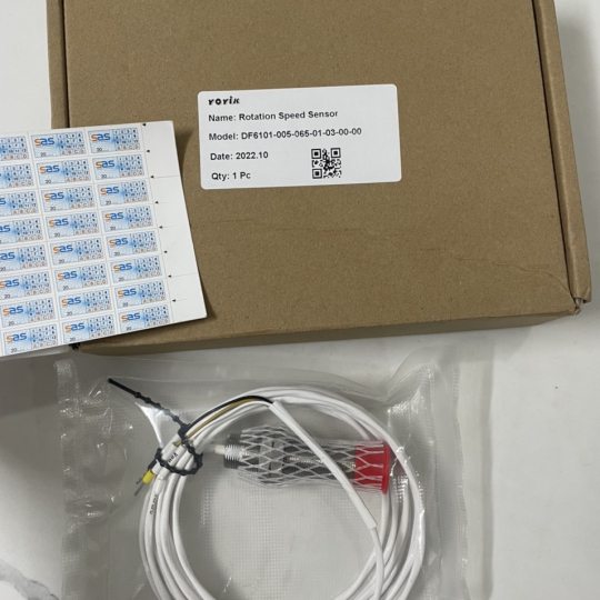
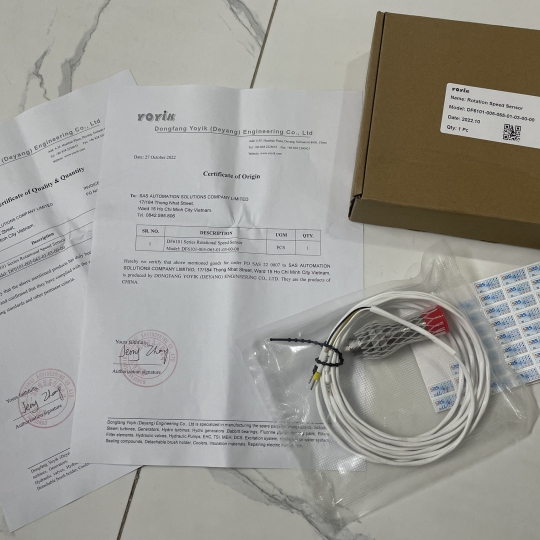
Cảm biến tốc độ DF6101-005-065-01-03-00-00 hãng Yoyik China
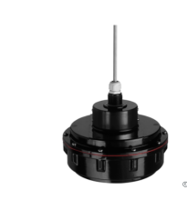
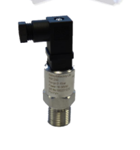
DF6101 Series Rotational Speed Sensor
Model: DF6101-005-065-01-03-00-00, Seri number: 20130522
http://www.yoyik.com/content/?6034.html
-
DF6101-005-065-01-03-00-00
-
Liên hệ
-
1819
- Thông tin sản phẩm
- Bình luận
DF6101 series magnetoelectric rotational speed sensor (also known as magnetoresistive type or variable-air type) is a commonly used speed sensor with high cost performance and wide usage. It can be used in the field of low cost consumer products and high precision speed measurement and control of aircraft engines.
Features:
Heat resistance, vibration resistance, impact resistance, can be used in harsh environment such asmoisture, oil and corrosive.
No movable part, is non-contact sensor, long service life
No power supply, simple installation, easy adjustment
Widely available, high reliability, good price
Operating Principle
DF6101 rotational speed sensor consists of magnet steel, soft magnetic armature and coil. The magnetic field (magnetic line) is emitted by magnet steel and returns to the other end of the magnet through armature and coil. When a ferromagnetic tooth passes through the sensor, the reluctance of the magnetic circuit will change once, and an alternating voltage signal will be induced inside the coil. Involute gear induces sine wave.
According to the electromagnetic induction principle, the AC voltage signal generated by the sensor, frequency f, is the product of the gear tooth number Z and the gear speed n. The measured frequency canbe obtained:
Rotation Speed n (r/min) = frequency f x 60
Number of gear teeth Z
Based on the principle of electromagnetic induction, the amplitude of the AC voltage signal generated by the sensor is directly proportional to the speed of the tooth passing. The more gear teeth, the faster the speed, the greater the amplitude of the signal, so the signal amplitude at low speed is very small. However when the speed is very high, the effect of weakening magnetic field of the coil is also enhanced, resulting signal amplitude being weakened. Therefore magnetoelectric sensor is usually used to measure the speed
signal of frequency 20Hz-10kHz. Gap Coil Magnet steel Cable Measuring Gear Armature Casing
DF6101 Series Rotation Speed Sensor
Technical Specification
| DC Resistance | 500Ω - 700Ω | Output Wave | Sine Wave (Involute Gear) |
| Insulation Resistance |
>50mΩ at 500V DC | Input Frequency |
20 ~ 10000hz |
| Output Amplitude | >100mv (P-P) at 20r/min & 1mm gap | Gear Requirement |
High Magnetic Conductive Steel |
| Working Temp. | Normal Temp.: -40~100℃ | Modules: ≥2 | |
| High Temp.: -20~250℃ | Involute or Equal Tooth |
Wiring Instruction
Cable end:
Gear and Installation Requirements
Gear:
①Tooth length: ≥4mm ②Tooth width: ≥4mm ③Tooth height: ≥4mm ④Tooth spacing: ≥4mm
Installation:
D: Installation gap: 0.8~1.5mm
Center of the armature must be corresponding to the center of the tooth.
Considerations
a) The cable shield of the sensor’s output wire must be reliably grounded.
b) The normal temperature type is not allowed to be used in strong magnetic field above 100℃.
c) The high temperature type is not allowed to be used in strong magnetic field above 250℃.
d) Avoid strong impacting during installation and transportation.
Manufacturer does not accept any liability for damages or measurement errors due to non-compliance with
above instruction.
http://www.yoyik.com/content/?6034.html
Sản phẩm cùng loại


Thông tin liên hệ
CÔNG TY TNHH GIẢI PHÁP TỰ ĐỘNG HÓA SAS
Mã số thuế: 0315763284
Địa chỉ: 409/48 Nguyễn Oanh, Phường 17, Quận Gò Vấp, TP Hồ Chí Minh,Việt Nam.  Xem bản đồ
Tên giao dịch: SAS AUTOMATION SOLUTIONS COMPANY LIMITED
Tên viết tắt: SAS AUTOMATION CO., LTD
Tag seo
Copyright © 2020 your name Designed by:Nina Co.,Ltd
online: 177
Trong tháng: 10000
Tổng truy cập: 4061008
