Loa thông báo E2S STEXS1RAC230DS2A1R STExS1F Alarm Horn Sounder E2S STEXS1RAC230DS2A1C. E2S STExL2FV100AS2A1R, E2S STExC1X05RDC024CS4A1R/R

0944911836 Ms. Duyên
0972835740 Ms. Hà
0385097045 Mr. Hiếu
0392468875 Ms. Anh
0707602728 Ms. Vân
Loa thông báo E2S STEXS1RAC230DS2A1R STExS1F Alarm Horn Sounder E2S STEXS1RAC230DS2A1C. E2S STExL2FV100AS2A1R, E2S STExC1X05RDC024CS4A1R/R
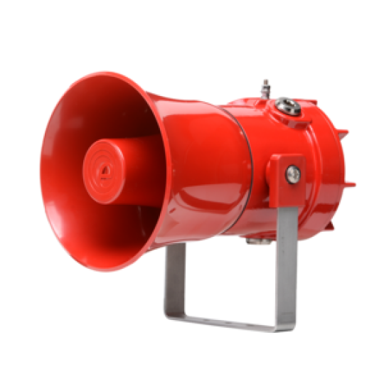
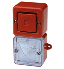
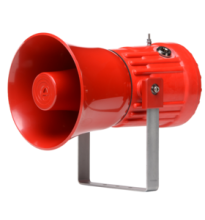
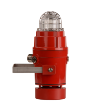
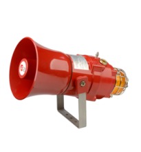
The STExS1F is a UL, cUL, IECEx and ATEX certified alarm horn sounder featuring a re-entrant flare horn. The robust 316L stainless steel enclosure is approved for Zone 1, 2, 21 & 22 explosion proof signalling applications.
-
E2S STEXS1RAC230DS2A1R
-
Liên hệ
-
38
- Thông tin sản phẩm
- Bình luận
Loa thông báo E2S STEXS1RAC230DS2A1R STExS1F Alarm Horn Sounder E2S STEXS1RAC230DS2A1C. E2S STExL2FV100AS2A1R, E2S STExC1X05RDC024CS4A1R/R
Description
Featuring 64 alarm tone sounds, each of the available 4 stage/channels can be remotely triggered. Class D amplification provides a high sound output at optimum operating current. The threaded flameproof joint, multiple cable entries and duplicated, pluggable termination simplifies both installation and routine maintenance. SIL1 & SIL2 Route 2H compliant to IEC61508 (2010) as standard, with optional diagnostic module for Route 1H SIL2 compliance. DNV type approved for exposed locations.
Part Codes
| Part Code: | Identifier: | Description: |
|---|---|---|
| Product type: | STExS1 | STExS1 alarm horn sounder |
| Horn type: | F | Flare re-entrant horn |
| Voltage: | DC024 AC230 |
11.5-54Vdc 100-240Vac |
| Cable entries:[e] | A B C D E F G |
3 x M20x1.5mm 2 × 1/2" NPT – adaptors 2 × 3/4" NPT – adaptors 2 x M25x1.5mm – adaptors 1 × 1/2" NPT – adaptor 1 × 3/4" NPT – adaptor 1 x M25x1.5mm – adaptor |
| Stopping plug/ adaptor material: [m] |
S | Stainless steel |
| Bracket material: [s] | 1 3 |
A4 316 Stainless Steel A4 316 St/St with Equip. Tag |
| Product version: [v] | A S T |
UL, cUL, ULC, IECEx, ATEX, DNV, Ex EAC INMETRO SIL1 & SIL2 Route 2H UL, cUL, ULC, IECEx, ATEX, Ex EAC, INMETRO SIL2 Route 1H with diagnostics SFF: >99% IECEx, ATEX, Ex EAC, INMETRO Telephone/Relay initiate |
| Product option: [o] | 1 Z X Y K V |
Standard product Custom alarm tone software – contact E2S Custom configuration – contact E2S Stage control Config. 4 Stage control Config. 5 (DC) and Config. 2 (AC) Stage control Config. 6 |
| Enclosure colour: [x] | R S |
Red Special – contact E2S for alternative enclosure colours |
| Accessories: | ||
| SP65-0001-A4 SP65-0003-A4 |
Pole Mount Bracket Kit St/St A4 (316) Sunshade – St/St A4 (316) |
| Alarm stage control: | ||
|---|---|---|
| Please review the installation manual and wiring schematics for remote stage control and EOL resistor monitoring configuration options: | ||
| Config. 1 [DC]: | Factory default. Common negative, positive switching. Up to 4 Alarm Stages. EOL monitoring Alarm Stage 1 only | |
| Config. 2 [DC]: | User setting. Common positive, negative switching. Up to 4 Alarm Stages. EOL monitoring Alarm Stage 1 only | |
| Config. 3 [DC]: | User setting. Common negative, positive switching activation of Alarm Stages 1 & 2 with EOL on both stages. Reverse polarity monitoring | |
| Config. 4 [DC]: | Product option ‘Y’. Independent activation of Alarm Stages 1 & 2 with EOL on both stages. Forward polarity monitoring | |
| Config. 5 [DC]: | Product option ‘K’. Horn continuously powered. Voltage free activation of up to 3 alarm stages | |
| Config. 6 [DC]: | Product option ‘V’. Independent activation of up to 4 Alarm Stages with EOL on all stages. Forward polarity monitoring | |
| Config. 1 [AC]: | Factory default. Up to 4 Alarm Stages. Stage 1 activated at power on. Stages 2, 3 and 4 via volt free contacts | |
| Config. 2 [AC]: | Product option ‘K’. Horn continuously powered. Voltage free activation of up to 3 alarm stages | |
Sản phẩm cùng loại


Thông tin liên hệ
CÔNG TY TNHH GIẢI PHÁP TỰ ĐỘNG HÓA SAS
Mã số thuế: 0315763284
Địa chỉ: 409/48 Nguyễn Oanh, Phường 17, Quận Gò Vấp, TP Hồ Chí Minh,Việt Nam.  Xem bản đồ
Tên giao dịch: SAS AUTOMATION SOLUTIONS COMPANY LIMITED
Tên viết tắt: SAS AUTOMATION CO., LTD
Tag seo
Copyright © 2020 your name Designed by:Nina Co.,Ltd
online: 221
Trong tháng: 10000
Tổng truy cập: 3987712
